My HRO-500 is, as far as I can tell, in original condition except that its 120V input mains transformer has been replaced to provide 240V operation.
However, I was nervous about applying mains voltage to the set. Firstly, the power inlet is two pin, there is no mains earth connection to the chassis or line fuse on the chassis. Secondly, the mains wiring is contained in a wiring loom together with internal dc and signalling cables and the consequences of a mains short burning out internal wiring was unthinkable.
So, I decided for the sake of both the receiver’s health and my own to run from a bench power supply while investigating the faults.
The first thing I did was to apply 12V dc to the 12V inlet on the rear of the receiver and measure the internal dc supplies. The 5V and 7.5V rails, which are stabilised by zeners, were spot on but the 10V and 11V rails were a couple of volts low. A simple ohm meter check around the power supply revealed a couple of carbon composite resistors had gone high resistance and replacing these restored the 10 and 11Vsupplies to within 0.75 of volt which I decided was probably good enough.
Next I pulled the muting transistor from its socket. This transistor applies AGC voltage to inhibit the second IF amplifier while the synthesised first local oscillator is trying to gain lock. I then applied 230kHz from a signal generator to the second IF amplifier which proved the back end of the receiver was working.
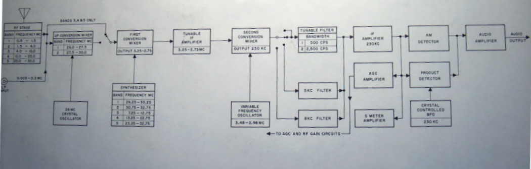 |
I now pulled the first local oscillator buffer transistor from its socket and injected 10.25MHz directly into the first conversion mixer from a signal generator. With an aerial connected this allowed me to tune the 7MHz amateur band. So I knew the receiver was pretty much working except for the synthesised first local oscillator.
My experience of working on phase locked loops is that you have to break the loop and slowly and methodically work round a stage at a time. So first thing I did was to pull out the dc amplifier transistor following the phase detector to remove any control voltage to the voltage controlled oscillator. I was going to pull out the sweep oscillator transistor too but when I scoped it I found it wasn’t working anyway.
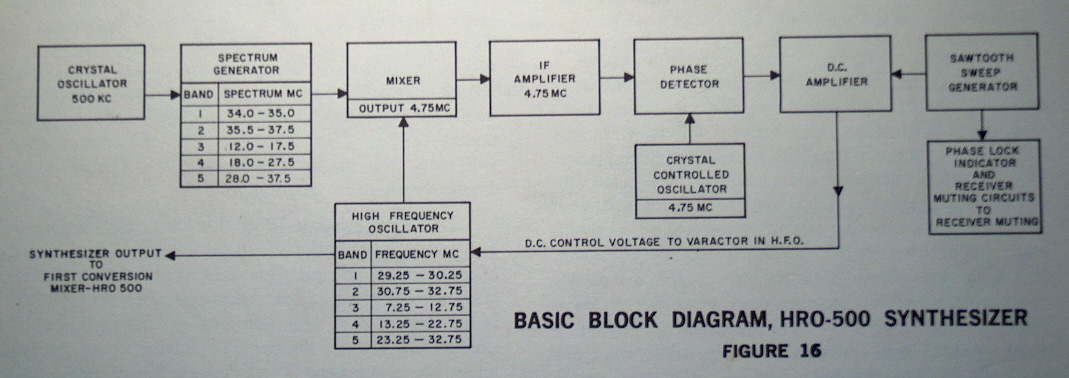 |
Having disabled the loop control, I started with the harmonic generator. This comprised a 500kHz crystal oscillator, transformer coupled blocking oscillator with limiting diodes across the transformer windings and a tuned buffer. The 500kHz crystal oscillator was running, I could see it on an oscilloscope, but there was precious little output from the tuned buffer. The handbook showed blocking oscillator base and collector waveforms. Those in my set showed some similarity if you used your imagination a bit. At this point I measured dc voltages and resistor values. Again, carbon composite resistors around the blocking oscillator and buffer were the problem as they had gone high resistance and I replaced three of these. Still no output though. Next I became suspicious of a 0.1uF coupling capacitor between the blocking oscillator and buffer amplifier. Lots of signal one side virtually nothing the other. On replacing this the tuned buffer amplifier collector waveform suddenly started to resemble that in the handbook. I don’t have a spectrum analyser so couldn’t look at the harmonic generator output in the frequency domain. Instead, I disconnected the harmonic generator feed to the rest of the synthesiser and connected it through a 30dB attenuator to a general coverage receiver (a Redifon R408). As I could hear nice strong signals every 500kHz up the hf bands from 12MHz to 30MHz I thought it was safe to assume the harmonic generator functional.
Now I moved to the high frequency voltage controlled oscillator. I connected my general coverage receiver via the attenuator to the point at which the oscillator enters the synthesiser’s 4.75MHz IF amplifier. Well there it was. On the top three band ranges I could tune the receiver in to the high frequency oscillator (the bottom two ranges were out of the tuning range of the receiver). It seemed strange though that when I had pulled the muting transistor previously, the free running high frequency oscillator hadn’t provided injection to the first conversion mixer. On investigation I found that the high frequency oscillator has two buffer amplifiers one which supplies the synthesiser IF and one which supplies the first conversion mixer. The transistor supplying the first conversion mixer was faulty and when I replaced it the receiver started to tune signals on its aerial. Of course the set was very unstable because the first synthesiser was not phase locked.
At this point I scoped through the three stages of the synthesiser’s 4.75MHz IF amplifier. Not surprisingly I didn’t get the waveforms shown in the handbook because I’d broken the control voltage feedback loop and as I discovered my sweep oscillator wasn’t working anyway. But I wasn’t seeing much at all even though I had harmonic generator and high frequency oscillator inputs. Before moving on I had to be confident that the 4.75MHz IF amplifier and phase detector were working. So I disconnected the harmonic generator and high frequency oscillator inputs and applied 4.75MHz from the signal generator. My fears were correct. There was virtually nothing at the input to the phase detector.
I decided to work backwards through the IF amplifier a stage at a time moving my signal generator injection point as I went. But first I’d do some dc and resistor value checks. These checks revealed that the 11V supply to the amplifier was down at about 8.5V and that there were a number of 100ohm and 1kohm resistors in the emitters that had gone high. I replaced the emitter resistors which was fine but it didn’t cure the low supply voltage. Tracing the 11V supply wiring back revealed a series 100ohm resistor under the chassis that was reading seriously high. Strange thing was I couldn’t find this resistor on the circuit diagram but non the less replaced it with a new 100ohm. - I think some unofficial mods were done to the set at some time. This gave me something close to 10 volts supply to the amplifier and I decide I’d live with this. Returning to the plan of injecting 4.75MHz from the signal generator one stage at a time I now worked back through my amplifier tuning the IF transformers as I went.
The 4.75MHz crystal oscillator which supplies the reference signal to the phase detector was working. I could tune it on my general coverage receiver. But with 4.75MHz injected into the re-aligned IF amplifier from the signal generator, the dc voltage measured on each of the phase detector diodes was very different and I suspected that the phase detector was out of balance. When I checked the two 10kohm phase detector load resistors one measured 9.5kohms and the other around 17kohms so I replaced both of them.
Now I returned the DC amplifier transistor to its socket and by adjusting the frequency of the signal generator could see a dc voltage change on its collector.
I was pretty confident now that the harmonic generator, high frequency oscillator and its buffers, 4.75MHz IF amplifier and phase detector were all working. So, I reconnected the harmonic generator and high frequency oscillator input to the IF amplifier.
Next thing to do was get that sweep oscillator working. Its purpose is to sweep the high frequency voltage controlled oscillator over a wide enough range so that at some point during the sweep its frequency, when mixed with a selected output of the harmonic generator, results in a signal close enough to 4.75MHz to be captured by the phase detector.
There were only four components in this circuit. Two resistors, which when measured were pretty close to the correct value, a unijunction transistor and a 1uF capacitor. I had a spare unijunction so unplugged and replaced this but this had no effect. That only left the capacitor and on replacing it the sweep generator sprang into life.
As I carefully adjusted the synthesiser tuning control, the phase lock light went out. Oh joy - it was locking!
But my pleasure at getting the synthesiser to lock was short lived. As I adjusted the synthesiser tuning to each 500kHz band on each range, I discovered that: on three ranges the set wouldn’t lock in on the highest frequency band at all; the calibration was significantly in error on some bands with locking occurring with the corresponding frequency obscured from the display window; and when returning to some bands the synthesiser locked to an adjacent band instead of the band displayed.
Well, all the covers were off which I guessed wasn’t helping matters. I found that replacing the harmonic generator and 4.75MHz IF amplifier covers had a marked effect on erroneous locking to adjacent bands but didn’t completely cure it.
I then started investigating the failure to lock on the highest frequency bands on each range. To do this I removed the sweep generator transistor, disconnected the harmonic generator and high frequency oscillator inputs to the 4.75MHz IF amplifier and injected 4.75MHz from a signal generator. This allowed me to look at the range of the control voltage produced by the dc amplifier as I varied the signal generator frequency about 4.75MHz. As this was somewhat less than the 2V to 7V range shown in the handbook I started looking at resistor values around the dc amplifier. Its emitter resistor had gone high resistance. After a significant struggle to get at it I managed to replace it.
The HRO-500 isn’t exactly built for maintenance. Some of the components are buried beneath switches and some involve taking the synthesiser sub assembly out completely which involves disengaging cord drives on tracked tuned circuits. As luck had it I just managed to get at the offending resistor by slackening off the screws holding the synthesiser sub chassis and pushing it backwards to allow just enough space to remove the IF amplifier’s bottom cover. I didn’t fancy re-cording. I then just managed to get my soldering iron in through the side of the receiver.
Replacing the dc amplifier emitter resistor extended the control voltage range but unfortunately when I put everything back together again it still wouldn’t lock on the highest three bands and of course the other problems were still there too.
To investigate the locking problem further, I now broke the dc control at the connection to the varactor diode and replaced it with a potentiometer across the 10V supply. This is when I discovered that with the high frequency oscillator free running it just didn’t have the range to tune the highest frequency bands. This and the other problems suggested that I would have to re-align the oscillator and its associated tuned buffer. I guess frequency determining components had aged and changed value over the years.
Alignment involved setting the control voltage to 5V (notionally mid range) with my potentiometer and then adjusting the oscillator and tuned buffer tracking.
I connected a frequency counter and oscilloscope to the output of the tuned buffer. On each of the high frequency oscillator’s five ranges, I first adjusted the synthesiser tuning control to the lowest band, then I adjusted the oscillator inductor for the required frequency reading on the counter, then I adjusted the buffer’s inductor for maximum amplitude. Having done this I repeated the process at the highest band on the range this time adjusting the oscillator and buffers trimming capacitors to obtain correct frequency and highest amplitude. I found that these adjustments on the oscillator interacted significantly. In the end I had to make a compromise on the oscillator inductor and trimmer adjustments which gave me the correct frequency for all band points occurring in a position as close as possible to the alignment of the corresponding figures in the display window. This whole process took hours!
Having done all this I removed the potentiometer and re-connected the dc control to the varactor. The set now locked on all bands with the correct band shown in the display window and the false locking had disappeared.
I now followed the alignment procedure given in the handbook for the 230kHz IF amplifier and pre-selector stages but found that these needed little adjustment.
I suspect that the receiver’s sensitivity may be down a little when compared against my Redifon and Racal receivers and is probably not up to its original specification. But nevertheless the HRO-500 is now usable. I guess there are more of those wretched carbon composite resistors in the RF and IF stages that have changed values and may be affecting the gain but given the nightmare of getting at them I’ve no plans to squeeze out the last dB in performance.
One final thing. I built a small 12V power supply, to modern safety standards, to power the receiver from its external dc connector. This is in a 6in x 4in x 2.5in box which I’ve attached to the rear of the receiver using the fixing screws for the receiver’s case.

